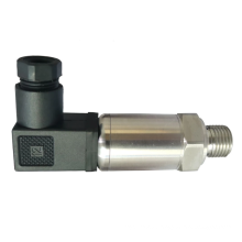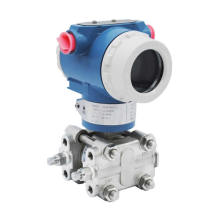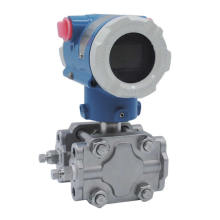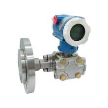


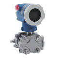
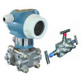
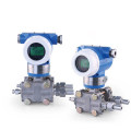
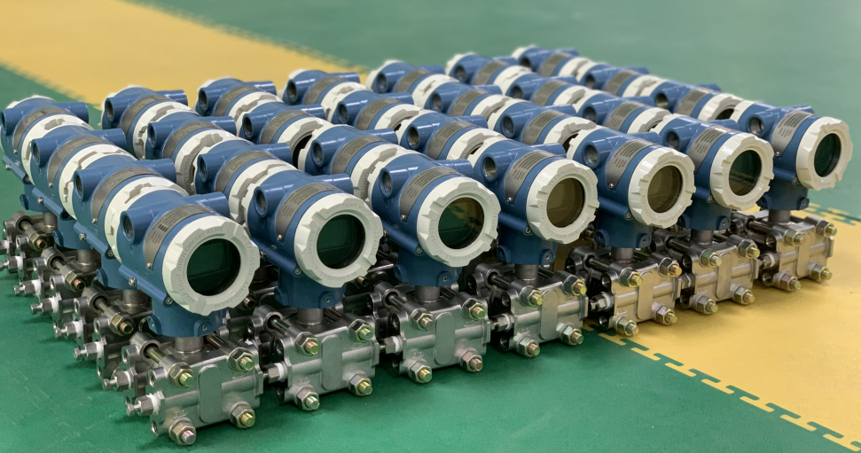
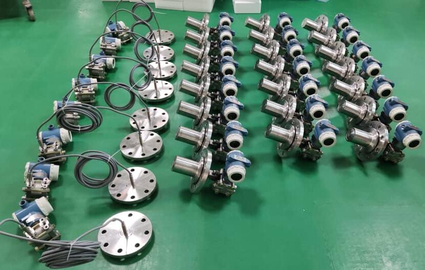
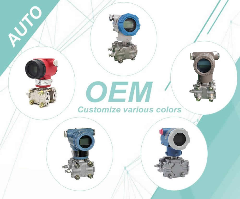
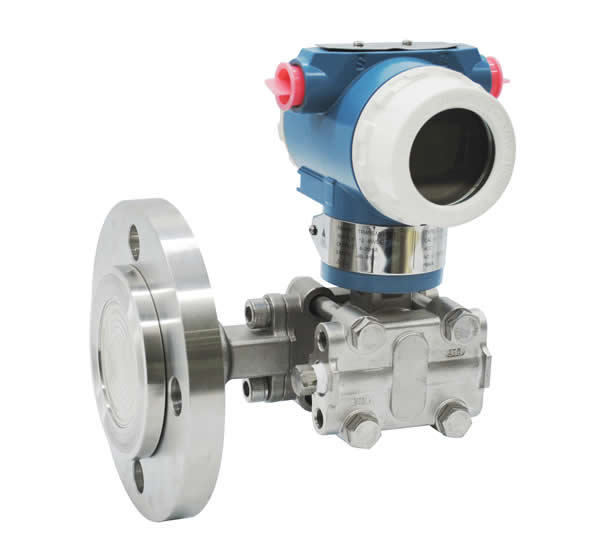
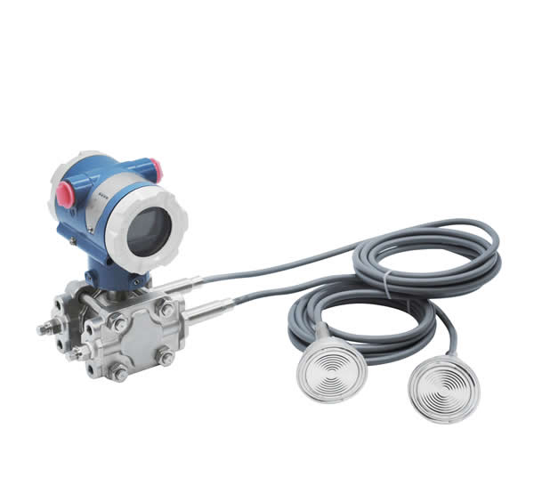
3051 Differential Pressure Transmitter With 3 Way Or 5 Way Manifold dp transmitter for orifice flowmeter
Product Description
3051 Differential Pressure Transmitter With 3 Way Or 5 Way Manifold dp transmitter for orifice flowmeter
Introduction
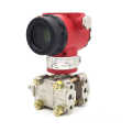
Differential pressure transmitter/pressure transmitter is a measure of the difference between the two ends of the transmitter ,output standard signal (eg 4 ~ 20mA, 1-5V) differential pressure transmitter and pressure transmitter with the general difference is that there are two pressure ports, the differential pressure transmitter is generally divided into positive and negative terminal end, under normal circumstances, Positive pressure side pressure should be greater than the negative pressure section.
Features:
1. Process Fluid: Liquid, Gas, Vapor
2. Applicat ion: Differential Pressure, Gauge Pressure,Absolute Pressure
3. Working Temperature: -25 to +95C
4. Current Output: 4 - 20 mA 2 wires Har t Protocol
5. Power Supply: 24VDC
6. Ambient Temperature: -25 to +240C
7. Process connections: 1/4 - 18 NPT or 1/2 - 14 NPT
8. Electrical Connections: 1/2”NPT or M20*1.5
9. Enclosure:IP65
10.Intrinsically Safe: ia II C T6
11.Explosion proof: d II B T5
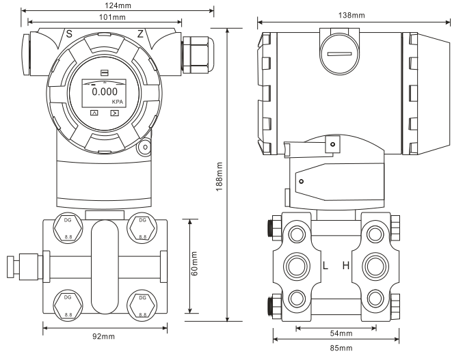
Dimension
Order sheet
| Name | Specification code | Explanation | ||
| 3051DP |
| 3051 Differential Pressure Transmitter With 3 Way Or 5 Way Manifold dp transmitter for orifice flowmeter
| ||
|
| 3 | 1.3-7.5KPa | ||
| 4 | 6.2-37.4KPa | |||
| 5 | 31-186.8KPa | |||
| 6 | 117-690KPa | |||
| 7 | 345-2068KPa | |||
| 8 | 1170-6890KPa | |||
| 9 | 3480-20680KPa | |||
| 0 | 6890-41370KPa | |||
| Output Signal | E | analog type 4-20mA | ||
| S | 4-20mA, HART Protocol Digital Communication | |||
|
Wetted Parts Material |
| Flange/Joint | Exhaust/Drain Valve | Diaphragm |
| 22 |
Stainless Steel |
Stainless Steel | 316L Stainless Steel | |
| 23 | Hastelloy C-276 | |||
| 24 | Tantalum | |||
|
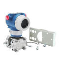
Mounting Bracket | B1 | Tube-type Curved Bracket (Tube ODΦ50~Φ60) | ||
| B2 | Board- type Curved Bracket | |||
| B3 | Tube-type Straight Bracket (Tube ODΦ50~Φ60) | |||
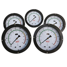
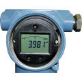
| Display Header (optional) | M2 | Linear Pointer Header (0~100% scale) | ||
| M3 | Square Root Instruction Header(0~100% scale) | |||
| M4 | LCD Header(0~100% linear display) | |||
|
Process Flange | D | The liquid discharge / exhaust at the back | ||
| D1 | The liquid discharge / exhaust at the side top | |||
| D2 | The liquid discharge / exhaust at the side bottom | |||
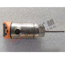
| Flange Joint | J | “D-shaped” Joint with “ M20*1.5” External thread | ||
|
| N | Joint with 1/2-14NPT taper pipe thread waist type | ||
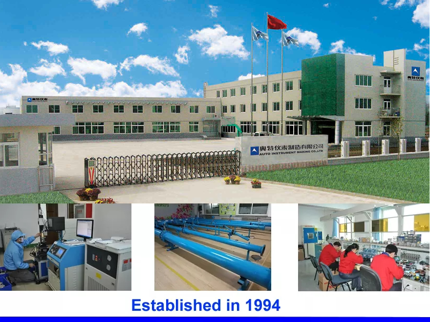
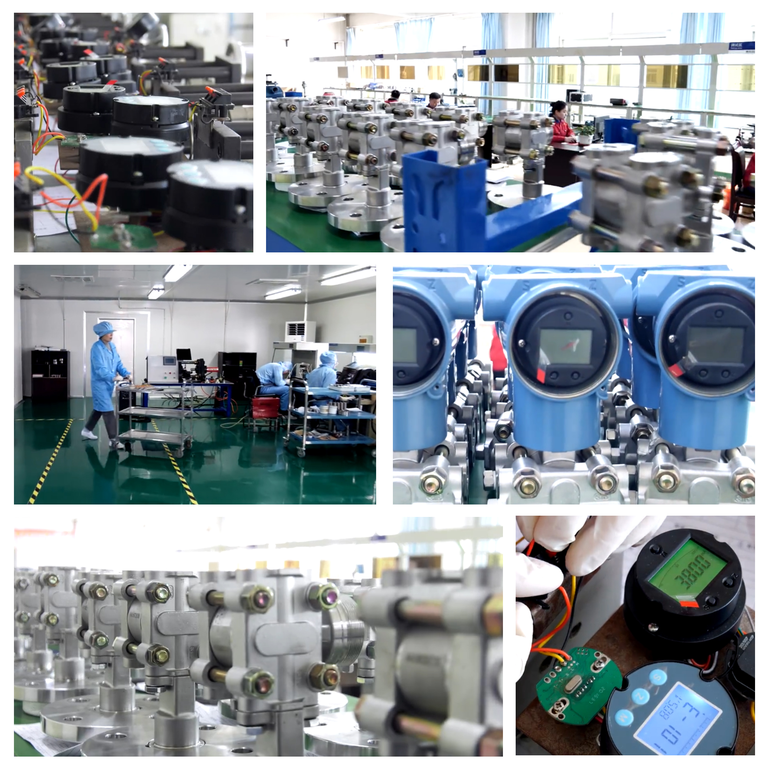
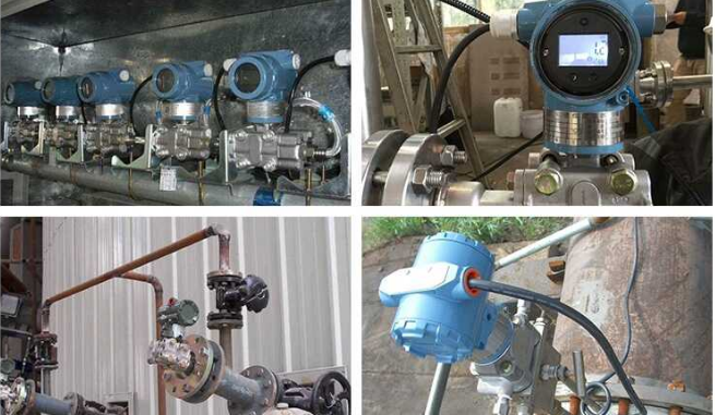
Our company

Site application

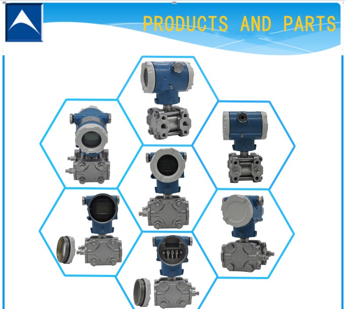
More details of other pressure transmitter, please click the flowing pictures!
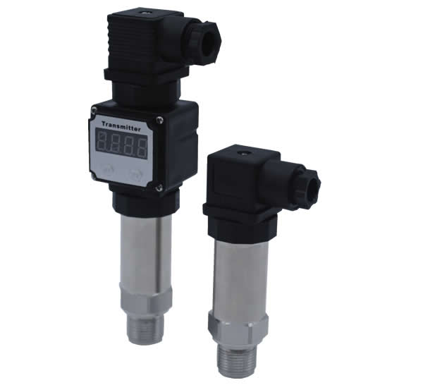
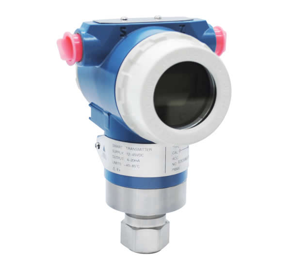


Product Categories : Pressure Transmitter > Gauge Pressure Transmitter
Premium Related Products